Limit switch box valve position feedback Thermostat wiring diagram honeywell switch limit fan heat diagrams hvac pump room wire ac systems t87 system control high programmable How the honeywell fan and limit switch works.
Wiring Diagram Limit Switch
Limit control How to use an external limit switch kit with a linear actuator Limit switch wiring connection dc load working
Honeywell thermostat diagramweb propane heat
Wiring diagram switch sensor occupancy limit ceiling aux sponsored linksTable fan wiring circuit diagram Wiring diagram limit switchSwitch limit wiring diagram motor relay switches control reversing ac direction electrical volt electric dpdt reverse circuit need spst awesome.
Limit switch connection/wiring with ac/dc load ii working of limitActuator switches actuators connection adjustable Solenoid namur povvalves pneumatic.


Table Fan Wiring Circuit Diagram - Wiring View and Schematics Diagram

How The Honeywell Fan And Limit Switch Works. - Youtube - Honeywell Fan

LIMIT CONTROL - JapaneseClass.jp
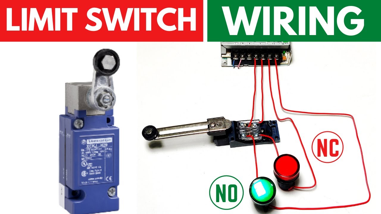
Limit Switch Connection/Wiring with AC/DC Load II Working of Limit
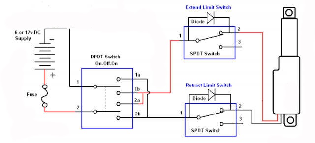
How To Use An External Limit Switch Kit With A Linear Actuator | Actuonix

Limit switch box Valve position feedback - Pneumatic valve China

relay - limit switches to control motor direction - Electrical
